MX 10 Luminance Key Modification
This modification is issued under the conditions of GPL copyright. It cannot be used for commercial gain, or reproduced in any form without including reference to its source.
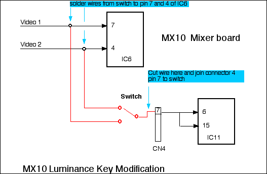
With analogue video, a luminance Key is the combination of 3 signals: background source, key source (the signal that "cuts the hole"), and insert source (the signal that "fills the hole"). Often the key source and the insert source are the same signal. The Panasonic MX10 luminance keyer allows you to cut a hole with video from source 1, Source 2, or the external camera input, but only allows you to fill it with the background colour video. This modification allows video from Source 1, or Source 2 to be used as the fill video, producing a full luminance key between two video sources.
Parts needed: One SPDT switch and a bit of wire.
Caution! This modification involves soldering onto surface mount components and should not be performed by anyone who is not experienced in this kind of work.
This simple mod is acheived by disconnecting the video from the white background video generator and substituting the video signal from source 1 and source 2, via a switch. The "White" button in the colour select section of the keyer then becomes the selector for the luminance key (you will loose your white background option, but this doesn't matter as white can still be selected as one of the background colours via the background colour selector). The purpose of the switch is to be able to switch the insert source (or fill video) between source 1 and source 2 independently of the key source (hole cutter). This allows the possibilty of 8 different combinations of keying when used in conjunction with the source select buttons and the bus switches. It is even possible to select the same input for background, key source and insert source, which, when used with the title effect options, produces a wierd outline effect.
Instructions:
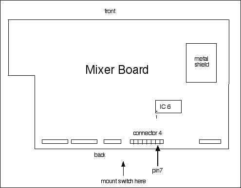
1. Dissassemble the MX10 by removing all the screws on the bottom that have arrow markers, and loosening the 5 case screws at the back. Don't remove any other screws.
2. The MX10 should come apart in two sections: the top and the bottom. The top section is the one we are interested in. It has a number of boards. The one on top with the small silver metal shield, and without the plastic cover is the mixer board. The space between the mixer board and the meter board (between the meter and the keying section of the control panel) is the best place to mount the switch.
3. After mounting the switch, cut the grey wire that runs to connector 4 - pin 7, on the mixer board, leaving enough length to run it from the connector to the centre pin of the switch.
4. Run wires from the other two pins of the switch to pins 4 and 7 of IC6 on the mixer board.